

Selecting the right automotive connector requires evaluating the application, electrical requirements, pin count and pinout, terminal and wire size, operating temperature, vibration, sealing, fluid exposure, mounting, locking structure, material, and compatibility. A connector should not be selected by appearance or pin count alone. The connector must match the electrical, mechanical, and environmental requirements of the specific vehicle system.
This blog breaks down the key selection factors step by step to help you choose the right automotive connector for your project.
What Is Automotive Connector Selection?
The objective of automotive connector selection is to identify interconnect components that meet the electrical, mechanical, and environmental requirements of a specific automotive application.
Key selection criteria include operating temperature range, vibration resistance, ingress protection (IP) rating, wire gauge compatibility, terminal material, connector locking and terminal retention mechanisms, resistance to automotive fluids and chemicals, mounting configuration, and material compatibility.
Proper connector selection helps ensure reliable power and signal transmission throughout vehicle electrical systems while reducing the risk of intermittent electrical contact, contact corrosion, and premature connector failure.
Why Is Proper Automotive Connector Selection Important?
Proper automotive connector selection helps ensure the safe and reliable operation of vehicle electrical systems. Connectors are critical interconnection points within automotive wiring harnesses, linking electronic control units (ECUs), sensors, actuators, and other electronic components.Automotive connectors are continuously exposed to multiple environmental challenges, including vibration, wide temperature fluctuations, moisture, dust, and exposure to oils or cleaning fluids. A connector assembly properly specified for its operating conditions can maintain reliable electrical contact under these harsh environments.
If engineers select connectors without adequately evaluating the actual operating conditions, terminals may develop intermittent electrical contact. Such intermittent connection faults can cause unpredictable electrical malfunctions and disrupt vehicle functions.
Connectors with appropriate sealing performance help prevent contaminants and liquids from entering the contact interface, reducing the risk of contact corrosion and extending the service life of the wiring harness system.Overall, careful automotive connector selection improves the long-term reliability of in-vehicle electronic systems and helps support overall vehicle safety.
Automotive Connector Selection Checklist
The objective of automotive connector selection is to identify interconnect components that meet the electrical, mechanical, and environmental requirements of a specific automotive application.
Key selection criteria include operating temperature range, vibration resistance, ingress protection (IP) rating, wire gauge compatibility, terminal material, connector locking and terminal retention mechanisms, resistance to automotive fluids and chemicals, mounting configuration, and material compatibility.
Proper connector selection helps ensure reliable power and signal transmission throughout vehicle electrical systems while reducing the risk of intermittent electrical contact, contact corrosion, and premature connector failure.
| What to Check | |
| Engine, transmission, sensor, lighting, ECU, body electronics, etc. | Sealed / non-sealed / required IP level |
| Wire-to-wire, wire-to-board, wire-to-device | Oil, ATF, coolant, chemicals |
| Required circuits Circuit assignment System voltage | Primary lock / secondary lock / CPA |
| Maximum operating current Compatible conductor size | Housing / seal / terminal materials |
| Terminal size and type | OEM number / drawing / sample |
| Mechanical environment | |
| Operating temperature range |
Step 1 — Identify the Automotive Application
First, identify which vehicle system the connector is installed in and its exact installation location within that system. Then verify the following:
Engine and Powertrain Applications
Designed to connect two separate wire segments, wire-to-wire connectors are commonly used for in-line wiring harness connections, particularly in cabin wiring and other low-stress in-vehicle electrical circuits.
- Engine
- Transmission
- Injector
- Sensor
- Actuator
- Window
- Door
- Mirror
- Wiper
- Seat
- Lighting
Safety and Chassis Applications
- ABS
- Wheel speed sensor
- ESC
- Airbag-related systems
ADAS and Infotainment Applications
- Radar
- Camera
- Parking sensor
- Display
- Infotainment
Identifying the application is the first step.
Step 2 — Choose the Right Automotive Connector Type
No single automotive connector is suitable for every system in a vehicle. The application environment and operating requirements determine the appropriate connector type. Common categories include wire-to-wire connectors, wire-to-board connectors, sealed connectors, non-sealed connectors, and sensor connectors.
Wire-to-Wire Connectors
Designed to connect two separate wire segments, wire-to-wire connectors are commonly used for in-line wiring harness connections, particularly in cabin wiring and other low-stress in-vehicle electrical circuits.
Wire-to-Board Connectors
Wire-to-board connectors provide an electrical connection between wires and a printed circuit board (PCB). They are commonly used when an automotive wiring harness needs to interface with in-vehicle control modules or electronic control unit (ECU) circuit boards.
Sealed Connectors
Sealed automotive connectors incorporate rubber seals and sealing components to help prevent the ingress of moisture, dust, road grime, and various automotive fluids.The engine compartment, wheel wells, exterior lighting assemblies, and chassis-mounted components are frequently exposed to harsh contaminants. Sealing structures help prevent corrosion at the electrical contact interface and maintain reliable electrical performance under demanding operating conditions .Sealed connectors should be used in locations exposed to water, dust, oil contamination, or significant temperature fluctuations.
Non-Sealed Connectors
Non-sealed automotive connectors do not incorporate dedicated environmental sealing features and rely on surrounding vehicle structures to protect the terminals from contaminants.They are suitable only for dry, fully protected interior locations away from splash water, moisture, and debris. Without adequate sealing protection, these connectors are vulnerable to corrosion and premature failure when installed in exposed areas.Non-sealed connectors should be selected only for in-vehicle applications where exposure to liquid ingress and dust contamination is not a concern.
Sensor Connectors
Automotive sensor connectors are designed with a compact form factor and optimized for low-noise signal transmission, making them suitable for in-vehicle sensor applications.Automotive sensors measure real-time parameters such as pressure, temperature, and position, then transmit low-level measurement signals to electronic control units (ECUs). Sensor connectors are designed to fit into space-constrained installations, withstand vibration, and help maintain signal integrity.
Sensor connectors are suitable for establishing reliable signal connections between automotive sensors and ECUs.
H2:Step 3 — Determine Voltage and Current Requirements
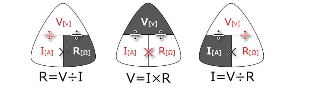
Voltage and current ratings are critical parameters that determine whether an electrical component can operate safely and reliably. Connector selection must therefore be based on the specific electrical requirements of the equipment. The process begins by confirming whether the equipment uses alternating current (AC) or direct current (DC), followed by determining the operating voltage and actual operating current.
Why Voltage Matters
Voltage is the fundamental operating parameter of electrical equipment and one of the most important criteria in component selection.
Voltage can be classified as alternating current (AC) or direct current (DC). AC equipment must be compatible with the standard mains voltage in the region where it operates. An incorrect voltage supply can cause abnormal operation or even permanent equipment damage. DC equipment operates across a wide range of voltage levels, from 1.5 V to 24 V and beyond. The rated voltage can typically be found on the power adapter label or equipment nameplate.
A supply voltage significantly below the rated value can result in inadequate performance. The equipment may fail to start, operate with insufficient power, or produce unstable output. Conversely, excessive voltage can overstress electrical circuits and damage motors, LEDs, and other sensitive electronic components.
Voltage also directly affects current consumption. When the supply voltage deviates from the design specifications, the actual operating current may differ from the expected value, depending on the load characteristics. Incorrect current estimates can lead to improper selection of power supplies, multimeters, and interface components for microcontroller-based control systems.
Why Current Rating Matters
Rated current is the maximum current that an electrical device, wire, or connector can safely carry under specified operating conditions. While voltage determines whether equipment can operate as intended, the current rating defines the safe current-carrying limit and helps prevent overheating and component damage.
Every electrical component has a specified current rating. If the actual operating current exceeds this limit, the resulting resistive heating can become excessive. Overheating may melt plastic connector housings, damage internal circuits, and burn out terminals, wires, or power supplies. In severe cases, overcurrent can also create a fire hazard.Actual current consumption often varies dynamically with operating conditions. For example, a motor’s inrush current at startup can be significantly higher than its steady-state operating current. Therefore, matching components to the nominal operating current alone is insufficient; short-duration current peaks must also be taken into account.
When selecting automotive connectors, wiring harnesses, and power supplies, their current ratings must be sufficient for the maximum expected circuit current under the specified operating conditions. Even when the operating voltage is fully compatible, components with insufficient current-carrying capacity cannot safely handle the load.
Verifying current ratings helps protect the entire electrical system against unexpected thermal damage and supports long-term operational reliability.
What Happens If the Connector Is Underspecified?
Rated current is the maximum current that an electrical device, wire, or connector can safely carry under specified operating conditions. While voltage determines whether equipment can operate as intended, the current rating defines the safe current-carrying limit and helps prevent overheating and component damage.
Every electrical component has a specified current rating. If the actual operating current exceeds this limit, the resulting resistive heating can become excessive. Overheating may melt plastic connector housings, damage internal circuits, and burn out terminals, wires, or power supplies. In severe cases, overcurrent can also create a fire hazard.
Actual current consumption often varies dynamically with operating conditions. For example, a motor’s inrush current at startup can be significantly higher than its steady-state operating current. Therefore, matching components to the nominal operating current alone is insufficient; short-duration current peaks must also be taken into account.
When selecting automotive connectors, wiring harnesses, and power supplies, their current ratings must be sufficient for the maximum expected circuit current under the specified operating conditions. Even when the operating voltage is fully compatible, components with insufficient current-carrying capacity cannot safely handle the load.Verifying current ratings helps protect the entire electrical system against unexpected thermal damage and supports long-term operational reliability.
Signal vs Power Connections
Automotive connectors are primarily used in two types of circuits: signal circuits and power circuits, each with distinct design requirements. Engineers should not evaluate all automotive connectors based solely on their rated current.
Signal circuits transmit low-level measurement signals and control data between sensors and electronic control units (ECUs), typically at very low current levels. The key design priorities for signal connectors are maintaining signal integrity, minimizing electrical noise interference, and ensuring stable contact resistance rather than maximizing current-carrying capacity.
Power circuits supply electrical power to loads such as vehicle lighting, pumps, and actuators. These circuits carry higher continuous currents or transient currents, including inrush current. Power connectors must provide adequate current-carrying capacity, effective heat dissipation, and robust contact structures to handle the electrical load safely and reliably.
When selecting an automotive connector, first determine whether the application involves signal transmission or power delivery. Even if a signal connector appears to have the same pin configuration as a power connector, it may not be suitable for power applications due to differences in contact design, current-carrying capacity, and thermal performance.
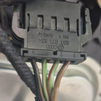
Step 4 — Determine Pin Count and Pinout
How Many Pins Do You Need?
You can determine the circuit count by checking the number of terminal cavities in the connector. Each cavity represents one terminal position, with positions numbered sequentially.
Why Pin Count Alone Is Not Enough
Matching Pin Count Does Not Guarantee Compatibility
Using a connector with the same number of pins does not necessarily mean it is compatible.
Before confirming compatibility, verify the following specifications:
- Pin Position
- Pin Assignment (Pinout)
- Terminal Type
- Connector Housing
- Locking Mechanism
- Wire Gauge
What Is a Pinout?
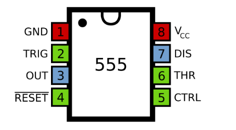
Pin 1 → Power Pin 2 → Ground Pin 3 → Signal Pin 4 → Signal / Control
Step 5 — Select the Correct Terminal and Wire Size
Why Terminal Selection Matters
Terminals are the conductive core of an automotive connector and directly affect electrical contact performance. Incorrect terminal selection can increase contact resistance under vibration and thermal cycling, leading to overheating, voltage drop, and intermittent electrical faults.Signal circuits and power circuits require different terminal designs to meet their respective electrical requirements. In addition, the terminal must be compatible with the wire gauge to ensure a reliable crimp connection.Proper terminal selection helps mitigate fretting corrosion and maintain stable electrical connections throughout the vehicle’s service life.
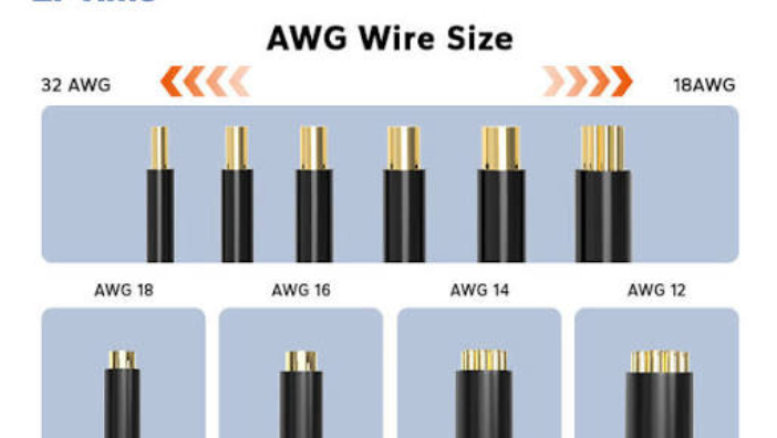
How to Match Terminal and Wire Gauge
Terminal-to-wire compatibility must be determined according to the wire gauge range specified in the terminal datasheet. An undersized wire may result in an inadequate crimp connection and insufficient mechanical retention, while an oversized wire can deform or split the terminal’s crimp barrel.
Power circuits and signal circuits typically use different wire gauges and therefore require terminals with the appropriate specifications. Proper terminal-to-wire matching helps ensure adequate crimp strength and low contact resistance, reducing the risk of fretting corrosion, overheating, and intermittent electrical contact under vehicle vibration.
Crimp Connection Considerations
During crimping, use crimping tooling compatible with the terminal specifications and wire gauge. A properly formed crimp consists of two sections: the conductor crimp and the insulation crimp. These provide a low-resistance electrical connection and mechanical strain relief, respectively.
After crimping, perform a visual inspection and, where required, conduct pull-force testing to verify crimp quality and mechanical strength. Crimping defects can progressively deteriorate under vibration and thermal cycling, eventually leading to overheating and intermittent electrical contact.
Terminal Retention
Connector housing compatibility does not necessarily guarantee terminal compatibility. The terminal retention mechanism is designed to secure the terminal inside the housing and prevent terminal back-out. Even if a terminal can be inserted into the housing, the retention mechanism may not provide a reliable lock. Under vibration and thermal cycling, terminals may gradually back out of the housing, leading to increased contact resistance, overheating, and intermittent electrical contact.
Terminal retention performance must be verified through testing of the matched housing-and-terminal assembly. Compatibility should never be determined solely by matching external dimensions or physical fit.
Step 6 — Evaluate Operating Temperature
The key to determining the required operating temperature range of an automotive connector is to evaluate its installation location:
- Interior
- Exterior
- Engine compartment
- Transmission
- Battery / electronics
Operating temperatures vary depending on the installation location.
How Temperature Affects Connector Materials
Thermal cycling is a critical environmental stress factor for automotive connectors, affecting the connector housing, terminals, and seals in different ways.
Plastic Housing: The housing positions the terminals and provides mechanical protection. High temperatures can reduce material stiffness, causing softening and deformation. At low temperatures, increased material brittleness can make the housing more susceptible to cracking under vibration. Materials such as PA66 are selected in different grades to meet the temperature requirements of specific applications.
Metal Terminals: Metal terminals expand and contract with temperature changes. Repeated thermal cycling can alter contact force, loosen the contact interface, and increase contact resistance, potentially causing intermittent electrical faults. High temperatures can also accelerate oxidation and degradation of terminal plating.
Elastomeric Seals: Seals prevent moisture and contaminants from entering the connector. High temperatures accelerate rubber aging and can cause irreversible compression set. Low temperatures can cause seals to harden, reducing their ability to maintain effective contact with mating surfaces. Both conditions can compromise sealing performance and weaken the environmental protection barrier.
Therefore, when selecting an automotive connector, verify the temperature ratings of the housing material, terminals, and sealing components to ensure that the complete connector assembly can withstand the intended operating temperature range.
Why Thermal Cycling Matters
Considering high-temperature resistance alone is insufficient. Connector reliability depends on the combined effects of actual operating temperature, repeated thermal cycling, and long-term exposure duration.
During vehicle operation and parking, ambient temperatures fluctuate continuously. Each temperature change causes the connector housing, terminals, and seals to expand and contract. Over the vehicle’s service life, accumulated mechanical stresses can gradually degrade the materials and components of the connector assembly.
Even if a connector can withstand high temperatures for a short period, repeated temperature fluctuations can still loosen the mating interface, compromise sealing performance, and contribute to fretting corrosion.Reliability testing should therefore go beyond single-point high-temperature tests. It should reproduce the actual operating temperature range, thermal cycling frequency, and exposure duration encountered in the intended automotive application.
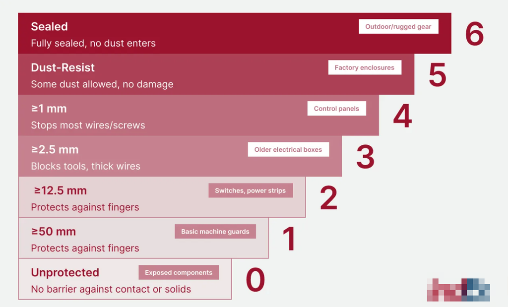
Step 7 — Determine Sealing and IP Protection Requirements
The key to determining whether a sealed or non-sealed automotive connector is suitable is to first identify its installation location within the vehicle system. Start by determining whether it is installed in:
- Interior
- Exterior
- Engine compartment
- Transmission
- Battery / electronics
IP54 / IP65 / IP67 / IP68
Select the required protection level according to the installation environment and specified test conditions.
Key Characteristics:
IP54
IP65
IP67
IP68
Why Seal Design Matters
Material selection is the first step. Engineers must evaluate physical properties such as hardness and water absorption, resistance properties such as ozone resistance, chemical resistance, abrasion resistance, and temperature resistance, as well as mechanical properties such as tensile strength, compression set, and resilience. These performance requirements must be balanced with manufacturing process requirements and cost constraints.
Next, evaluate the actual service conditions. Determine the operating temperature range, exposure duration, and chemical media that the sealing component may encounter. Distinguish between static applications, where there is no relative movement between sealing surfaces, and dynamic applications involving movement or vibration. These factors collectively affect sealing performance.
Assembly compression force and loading direction must also be verified. A seal designed for a specific compression force and loading direction may experience significantly reduced sealing performance if the assembly pressure or direction of loading changes. Friction during connector mating and insertion should also be evaluated. Seal geometry, material hardness, and lubrication methods can be optimized to control insertion friction.
During the design stage, account for the full tolerance range of the assembly. Both maximum and minimum assembly clearances must be considered, including the manufacturing tolerances of the connector housing. Seals can be retained mechanically or bonded with adhesive. Mechanical retention must not restrict the seal’s intended compression, while adhesive bonding requires careful consideration of bond-line thickness and compatibility between the sealing material and the substrate.
The design of angled joints and corners is another important consideration. A molded, one-piece corner generally provides better durability but involves higher manufacturing costs. Heat-welded or heat-fused joints offer a cost advantage but may have lower overall durability than a one-piece molded design.
Step 8 — Consider Vibration and Mechanical Stress
Where Is Vibration a Concern?
The engine, transmission, chassis, engine bay, and other dynamic components represent some of the most severe vibration environments within a vehicle. Prolonged exposure to vibration and mechanical shock may cause latch fatigue, terminal displacement, loss of contact force, and fretting corrosion. Automotive connectors installed in these areas require robust primary locking, secondary locking (CPA/TPA), and anti-fretting contact designs to ensure secure mating, stable terminal retention, and reliable electrical performance throughout the vehicle lifetime.
- Engine
- Transmission
- Chassis
- Under-hood
- Moving components
How Vibration Affects Terminals
Vibration ↓ Micro-Movement ↓ Terminal Movement ↓ Contact Instability ↓ Intermittent Connection
Which Features Improve Retention?
A robust multi-locking system improves mating retention and long-term connection reliability for automotive connectors. The primary locking mechanism secures the initial connector engagement, while the secondary lock provides additional reinforcement to maintain terminal positioning. The CPA (Connector Position Assurance) acts as a secondary safety feature to prevent accidental latch release and verify full connector engagement. In addition, the terminal retention system minimizes individual terminal back-out under vibration and thermal cycling conditions. Together, these locking mechanisms help maintain secure electrical connections and prevent connector separation or terminal displacement throughout the vehicle service life.
- Primary lock
- Secondary lock
- CPA
- Terminal retention
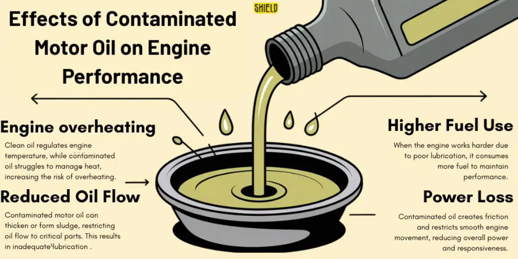
Step 9 — Evaluate Exposure to Oil, ATF, Water and Chemicals
When evaluating the environmental compatibility of an automotive connector, engineers must assess its exposure to water, moisture, engine oil, automatic transmission fluid (ATF), coolant, and other automotive fluids. Fluid compatibility depends on the connector housing material, sealing components, terminal plating, operating temperature, and exposure conditions. Not all automotive connectors are inherently resistant to oil or other automotive fluids. Before selecting a connector, verify material compatibility with the intended operating environment to prevent fluid-induced degradation and premature failure.
Moisture can promote terminal corrosion, automotive fluids can degrade sealing components and connector housings, and elevated temperatures can accelerate material deterioration.
Step 10 — Select the Right Connector Materials
Connector Housing Materials: Common housing materials include glass-fiber-reinforced polyamide 66 (PA66-GF) and glass-fiber-reinforced polybutylene terephthalate (PBT-GF). These materials are widely used in automotive connectors to meet a range of electrical application requirements. They provide mechanical strength, heat resistance, and chemical resistance, with the appropriate material grade selected according to the operating conditions.
Sealing Materials: Sealing materials are selected according to the environmental conditions and the fluids they may encounter. Their primary function is to prevent the ingress of moisture and contaminants. Key selection criteria include compression set, temperature resistance, aging resistance, and compatibility with automotive fluids.
Terminals and Plating: The terminal base material provides electrical conductivity and mechanical spring properties, while the plating helps protect against corrosion and, depending on the plating system and operating conditions, mitigate fretting corrosion. Tin, nickel, or gold plating can be selected according to the electrical requirements and operating environment.
Matching Materials to the Application: No single material is suitable for every automotive application. The connector housing, sealing material, terminal base material, and terminal plating must be evaluated as a complete system, taking into account operating temperature, vibration, fluid exposure, and other environmental conditions.
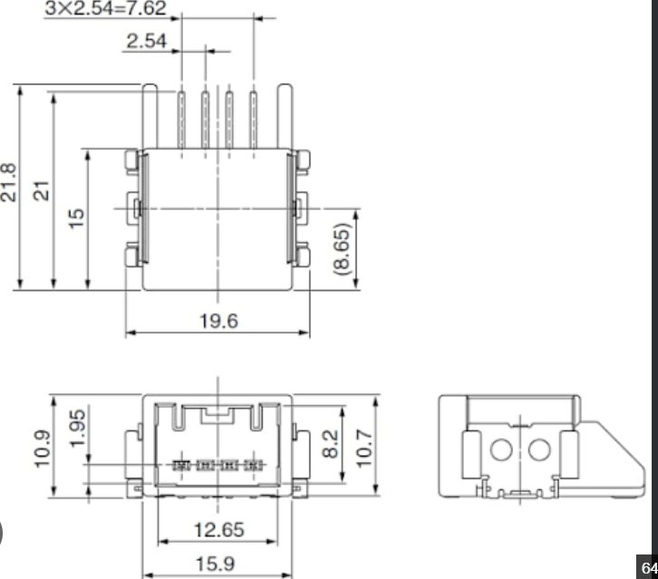
Step 11 — Check Mechanical Dimensions and Mounting
After that, check the following:
- Connector Mating Interface
- Panel Mounting
- PCB Mounting
- Mounting Dimensions
- Available Installation Space
Even if a connector has the correct electrical configuration, mismatched housing dimensions, mounting interfaces, or mating interfaces can still lead to mechanical failure.
Step 12 — Verify OEM Compatibility
Finally, verify OEM compatibility, a key purchasing requirement. This typically involves checking the following:
- OEM Part Number
- Connector Series
- Pin Count
- Pinout
- Terminal
- Wire Gauge
- Seal
- Locking Structure
- Mounting
FAQ
Choose an automotive connector based on its application, electrical requirements, mechanical interface, terminal configuration, operating environment, and OEM compatibility requirements.
Consider current and voltage requirements, pin configuration, housing dimensions, terminal type, wire gauge, temperature range, sealing performance, vibration resistance, and locking structure.
No, automotive connector compatibility also depends on housing geometry, terminal specifications, pin assignments, locking mechanisms, sealing design, and mating interface.
Check the connector’s specified IP rating, sealing structure, installation conditions, and validated test requirements rather than assuming that a rubber seal guarantees waterproof performance.
Verify an OEM replacement by comparing the original part number, mating interface, housing dimensions, terminal configuration, wiring assignments, locking structure, and environmental specifications.
Yes, clear photos showing the mating face, wire-entry side, side profile, markings, and pin layout can help identify a potential match, but final compatibility may require part numbers, measurements, or physical samples.
Conclusion
When purchasing automotive connectors, be sure to ask the supplier whether they offer the following:
- Dimensional Inspection
- Terminal Inspection
- Mating Test
- Electrical Performance Test
- Sealing / Waterproof Test
- Temperature Test
- Vibration Test
The right automotive connector is selected by matching application, electrical requirements, pinout, terminal and wire size, temperature, vibration, sealing, fluid exposure, mounting, materials, and compatibility.
When OEM information is incomplete, a connector photo, drawing, pin count, application and wire specification can help suppliers identify a suitable solution.
