

Connector Pinout & Wiring Guide for Automotive Applications
After years of wiring harness repairs, vehicle modifications, and ECU swaps, I’ve seen countless seemingly simple faults caused by connector pinouts. Wiring diagrams and specifications may look correct on paper, yet problems emerge during actual vehicle installation: intermittent CAN communication, modules burning out immediately after power-up, or persistent sensor signal drift faults after sensor replacement. In most cases, the root cause isn’t an incorrect drawing, but overlooked details such as diagram interpretation, male and female connector viewing angles, and terminal assembly practices.
This guide draws on years of hands-on vehicle repair and wiring harness rework experience. It is intended for wiring harness technicians, harness manufacturers, vehicle modification specialists, and procurement engineers. If you need specification-matched sealed connector housings, terminals, and seals, explore our product catalog for suitable solutions.
What Are Automotive Connector Pinouts and Pin Assignments?
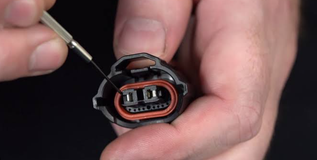
A pinout identifies the number, electrical function, rated voltage, and signal type associated with each connector cavity. A pin assignment defines how power, ground, analog signals, CAN/LIN communication lines, and actuator outputs are arranged within a fixed cavity layout.
One of the most common mistakes beginners make is confusing cavity numbers with electrical functions. Cavity numbers indicate physical positions, while the cavity layout describes the housing’s geometric arrangement. A vehicle wiring diagram illustrates electrical connections throughout the vehicle; it should not be used directly as a connector end-view diagram.
In the automotive industry, connector performance requirements are addressed by standards such as SAE/USCAR-2. Connector housings commonly use glass-fiber-reinforced materials such as PA66-GF35, while operating temperature ranges and sealing ratings, such as IP67 or IP68, vary by product and must be verified against the relevant datasheet.
Here is a practical lesson from real-world wiring work: the cavity views of male and female connectors are often mirror images of each other. The drawing convention typically defines the end view as looking into the mating face, not at the wire-entry side. I’ve seen apprentices compare a female connector drawing directly against a male connector harness, reverse the left and right positions, and swap CAN-H and CAN-L—then spend hours troubleshooting the resulting communication fault.
Common Automotive Connector Types and Pinout References
Deutsch DT Series Connectors
The Deutsch DT series is widely used in off-highway equipment, construction machinery, engine peripheral sensors, and powertrain wiring harnesses. Common configurations include 2-, 3-, 4-, 6-, 8-, and 12-position connectors. These sealed connectors feature wedge-locking mechanisms and multiple keying options, such as A, B, C, and D. Housings with the same number of positions but different keying configurations may not mate with each other. The cavities are arranged in a matrix, and the triangular marking on the housing can serve as a reference for cavity 1.
Practical experience: The DT housing defines the cavity geometry but does not provide a universal pinout. Some technicians find a DT 4-position connector diagram online and install the connector without verifying the circuit assignments, resulting in mismatched power and signal connections. Identifying the correct housing is also essential: DT06S is a wire-side receptacle housing, while DT04P is a plug housing commonly used on the equipment side. Common rework causes include selecting the wrong terminals and forgetting to install single-wire cavity plugs. After vehicle washing, moisture ingress can gradually oxidize the terminals, causing intermittent contact faults that appear when the engine is cold and disappear as it warms up.
AMPSEAL Series Connectors
AMPSEAL connectors are commonly used in body control modules (BCMs), door modules, lighting systems, and seat control modules. Popular configurations include AMPSEAL 23 and AMPSEAL 35. Their staggered, multi-row cavity layouts can make it easy to miscount rows or identify the wrong cavity.
Practical experience: These connectors often carry multiple LIN communication signals and low-current switching signals, making secure terminal retention essential. I do not recommend casually depinning terminals and rearranging their positions. I once encountered a vehicle where a technician changed the AMPSEAL terminal sequence to simplify wire routing. After installation, the power windows and door locks failed intermittently. The diagnostic trouble codes indicated only a module communication fault, without directly identifying the wiring harness as the cause, making troubleshooting time-consuming. Pin logic is tied to the module’s internal circuitry and hardware configuration; rearranging terminals is not simply a matter of changing wire positions.
Ignition Coil Connectors
Common ignition coil connectors have three or four positions and typically use compact sealed housings. They are frequently exposed to demanding powertrain operating conditions.
A typical three-wire configuration may include a 12 V ignition supply, ground, and an IGT ignition trigger signal. Some four-wire designs add an IGF ignition confirmation or feedback signal. However, the exact pin assignment varies by vehicle manufacturer and ignition system.
Practical tip: Although the general signal functions may be similar, wire order can differ between manufacturers and models. Before replacing a connector, I check the signals at the original connector rather than relying on a generic pinout. These connectors are often located near the exhaust, where prolonged heat exposure can cause terminal back-out and reduced contact spring force. Some engine misfire problems are caused not by a faulty ignition coil, but by poor electrical contact at the connector terminals.
ECU / TCM Multi-Position Connectors
Large ECU and transmission control module (TCM) connectors may contain dozens or more than 100 terminal positions. They can accommodate main power supplies, multiple ground circuits, analog sensor inputs, CAN bus communication, actuator outputs, and diagnostic K-line connections.
Key practical insight: The same housing may have completely different pin assignments across model years and vehicle configurations. Even ECUs using the same housing can have different reserved cavity functions in base and higher-specification versions. We supply compatible connector housings, terminals, and seals; original ECU pinout diagrams are generally OEM-controlled technical documents and are not typically provided by connector suppliers. One of the most serious repair mistakes is transferring a pinout from a different vehicle with a supposedly identical ECU.
Compact Sealed Sensor Connectors
Crankshaft position, camshaft position, pressure, and temperature sensors often use three-position connectors. Depending on the sensor design, a typical configuration may include a 5 V reference supply, a signal line, and a sensor ground.
A common beginner’s mistake: Sensor ground and chassis ground are not necessarily interchangeable. I have encountered several vehicles where technicians connected sensor ground directly to the vehicle chassis during wiring harness modifications. The result was persistent sensor reading fluctuations and unstable idling. Sensor ground serves as a reference for the control module’s measurement circuitry and must not be connected to chassis ground unless the vehicle manufacturer’s wiring diagram explicitly specifies that arrangement.
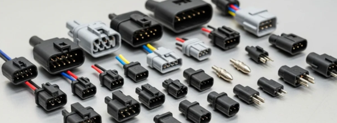
Compact Sealed Sensor Connectors
The first rule of reading a connector diagram is to identify the end view, looking directly into the mating face rather than at the wire-entry side. Locate the triangular marking, notch, or keying feature on the housing to establish the Pin 1 reference point, then follow the numbering sequence shown in the drawing. Next, account for the mirrored views of male and female connectors. My usual practice is to mark the Pin 1 position on the physical connector housing with a pen before comparing it with the diagram, rather than relying on memory or visual assumptions.
Wire colors should only be used as a secondary verification method, never as the sole basis for identifying a circuit. OEM wiring color conventions can vary between manufacturers, vehicle models, and production batches, so relying on color alone can lead to incorrect connections.
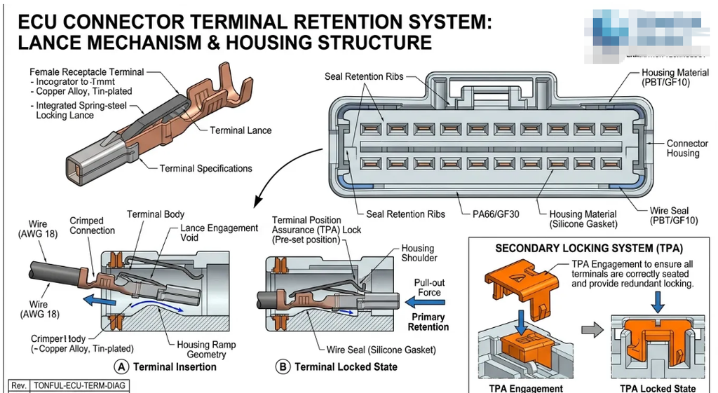
Essential workshop tools include a digital multimeter, a depinning tool matched to the connector model, and the appropriate crimping tool. The depinning tool must match the terminal cavity design. Forcing an oversized tool into a cavity can damage the internal locking lance, preventing the terminal from being securely retained. Under vehicle vibration, the terminal may gradually back out and cause intermittent faults that are difficult to diagnose.
My standard procedure after terminal replacement or harness modification is to disconnect power, perform continuity and insulation checks, and verify the wiring against the circuit diagram before reconnecting power and waking up the control module. Never power up the system or install the modified harness for testing until the relevant checks have been completed.
Common Automotive Connector Pinout Errors and Safety Risks
These are recurring problems encountered in real-world automotive repair, ranked by how frequently I have encountered them:
- Reversing male and female connector views, swapping CAN-H and CAN-L. Reversing the high-speed CAN differential pair can disrupt bus communication and cause intermittent or inconsistent fault codes. The fault may temporarily disappear after clearing the codes, only to return after driving. These intermittent communication issues can be particularly difficult to diagnose.
- Grinding off keying features to force incompatible connectors together. The keying features on DT and AMPSEAL connectors are designed to prevent incorrect mating. Grinding them down may allow an initial electrical connection, but vehicle vibration and road impacts can shift the terminals and cause intermittent contact. These faults often become more apparent in wet weather or on rough roads.
- Reversing power and ground connections. Reverse-polarity power can damage sensor electronics. Reversing the main ECU supply can destroy internal power-management components, potentially rendering the module unusable and resulting in costly repairs.
- Missing seals or damaged sealing rings. The sealing performance of a sealed connector depends on correctly installed individual wire seals and other sealing components. During terminal replacement, seals can become misaligned, damaged, or omitted entirely. Moisture can then enter through the terminal cavities, causing contact oxidation and corrosion. I have encountered many vehicles that developed warning lights after flooding or rain because the connector seals were incorrectly installed.
- Overloading signal terminals. Some technicians use a 5 V reference signal circuit to power a small load for convenience. However, reference circuits are designed for specific sensor loads and may have very limited current capacity. Overloading can damage the terminal or pull down the shared reference voltage, causing multiple sensors to malfunction simultaneously.
The key takeaway: The reliability of a sealed automotive connector depends on matching the housing, terminals, and seals as a complete system. Replacing a connector based on pin count alone can create serious compatibility problems and costly after-sales issues.
Automotive Connector Pin Testing with a Multimeter
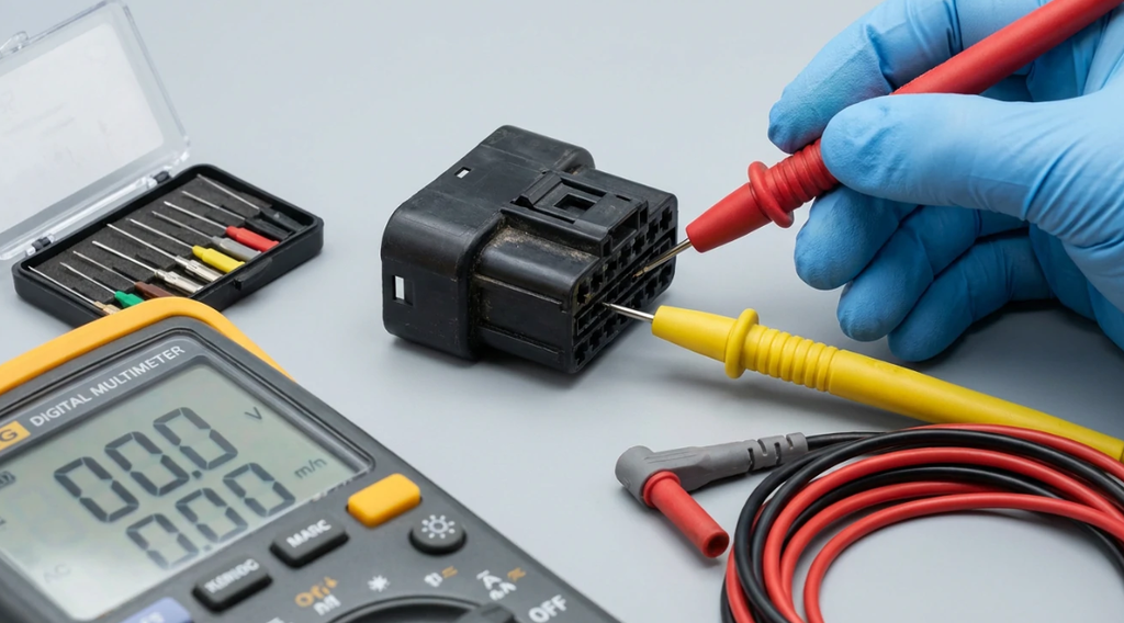
Before testing, follow the manufacturer’s power-down procedure, disconnect the battery negative terminal when required, and allow the control modules to enter sleep mode and discharge residual voltage. Some modules need several minutes to shut down fully, so do not begin testing immediately after disconnecting the battery.
- Continuity and Insulation Testing: Use resistance or continuity mode to check ground circuits and shield wires. Check insulation between pins and the housing only when the circuit is isolated and the test method is approved for the components involved. Low insulation resistance may indicate damaged insulation, moisture ingress, or an internal leakage path.
- Static Voltage Testing: After safely restoring power and waking the module, measure the constant battery supply, ignition-switched supply, and 5 V reference circuit according to the wiring diagram. If the 5 V reference deviates by more than 0.3 V from its specified value, investigate wiring voltage drop, terminal contact resistance, and other loads on the shared reference circuit before concluding that the sensor has failed.
- Basic CAN Bus Testing: With the network powered down and in the specified sleep state, measure the resistance between CAN-H and CAN-L when the manufacturer’s procedure permits it. A conventional high-speed CAN network with two 120 Ω termination resistors connected in parallel typically measures approximately 60 Ω. A reading near 120 Ω may indicate that only one termination is visible to the measurement; an open-circuit reading may indicate a disconnected path, while a reading near 0 Ω may indicate a short. When powered, CAN-H and CAN-L voltages vary with network state and transceiver design. Typical high-speed CAN levels are around 2.5 V on both lines when recessive, with CAN-H rising and CAN-L falling during dominant bits. Use the vehicle-specific specifications and an oscilloscope to confirm signal integrity.
- Critical Safety Rule: Never apply external voltage to ECU pins or sensor signal circuits unless the manufacturer’s test procedure explicitly requires it. Incorrect voltage injection can permanently damage control modules and sensors.
Important: A multimeter is useful for basic electrical checks, but it cannot reliably capture fast signal transitions, timing errors, or brief intermittent faults. For ignition triggers, crankshaft and camshaft position signals, and intermittent communication problems, an oscilloscope is often necessary to identify the fault.
Custom Pin Assignment Solutions for Specialized Wiring Harness Projects
While standard connector housings have fixed cavity layouts, pin assignments can be customized to meet specific project requirements. This is common in modified wiring harnesses, construction equipment rewiring, test harnesses, and agricultural machinery harnesses. For custom pin assignments, we always confirm four key details: connector housing model, terminal and wire gauge specifications, the electrical function of each pin, and whether unused cavities require sealing plugs. One detail customers often overlook is cavity sealing: unused cavities in sealed connectors must be fitted with the appropriate sealing plugs to maintain the specified sealing performance. Based on your pin assignment table, we can supply matching housings, terminals, sealing plugs, and wedges. For high-volume wiring harness manufacturers, we can also provide crimping reference parameters. To request a quote for a custom pin assignment layout, simply send us your pinout list.
Frequently Asked Questions (FAQ) About Automotive Connector Pinouts
A vehicle wiring diagram shows signal flow and connections between modules, while a connector pinout diagram focuses on the cavity positions and electrical functions of a specific connector. Both should be used together during repairs; neither should be relied on exclusively.
OEM ECU pinout information is generally available through official vehicle service manuals, manufacturer service information systems, or project-specific documentation. Connector suppliers typically provide housing and terminal specifications rather than proprietary vehicle-specific ECU pin assignments.
A properly designed sealing structure protects against water and dust without inherently interfering with electrical signals. CAN, LIN, and analog signals can operate normally when the connector meets the required electrical specifications. However, poor crimping, oxidation, or excessive contact resistance can still cause unstable signals, even in an IP68-rated connector.
Yes. Based on your pin assignment list and project requirements, we can supply matching connector housings, terminals, seals, and cavity plugs for customized wiring harness assemblies. Please provide the connector model, terminal specifications, and electrical function of each cavity so we can assess compatibility.
Conclusion
Automotive connector pinouts are more than simple numerical labels. They involve the integration of cavity geometry, terminal electrical specifications, and vehicle-level signal assignments. From years of experience in the automotive connector industry, one lesson stands out: drawings are fixed, but real-world vehicle operating conditions are not. Many rework issues arise not from incorrect drawings, but from overlooked details such as male-to-female mirrored views, polarization features, sealing assembly, and terminal locking tabs.
We offer in-stock compatible replacement connectors for Deutsch DT, AMPSEAL, ignition coils, and multi-position sealed ECU/BCM applications, along with matching housings, terminals, and seals designed with reference to applicable USCAR automotive requirements. If you need pinout verification, sample selection, or bulk component supply, submit your connector model and pin assignment requirements to request a quote.
